Reviving and repairing a Sharp MZ-700
I recently acquired a second Sharp MZ-700 that was in a rather poor state. I had no idea whether or not it could be salvaged when I bought it, but I thought it might be fun to try. A secondary reason for buying it was to experiment with alternatives to the inbuilt cassette tape deck. As with all vintage electronics, there is always a chance such experiments go badly wrong – and I really didn’t want to risk my other MZ-700.
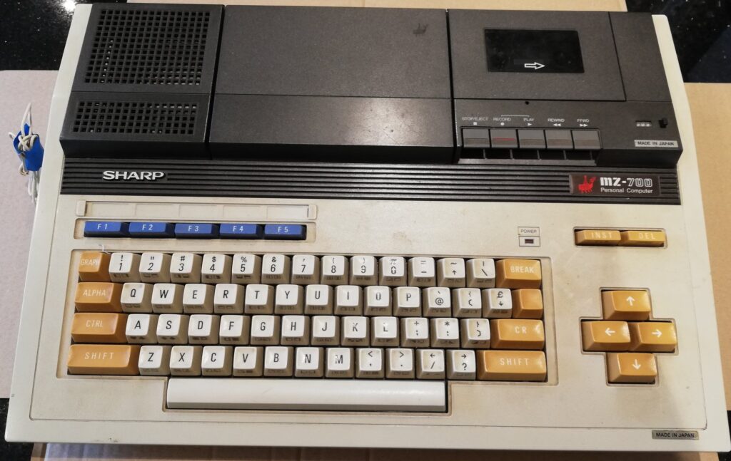
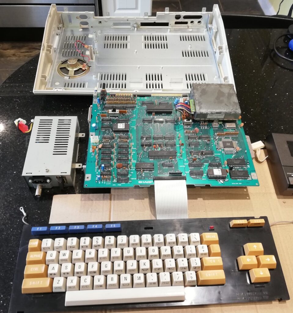
Here’s a photograph of the MZ-700 before I started my restoration efforts. Like my orignal machine, this is a MZ-721. It doesn’t come across in the photograph very well, but the keyboard was disgusting. There were also a couple of mystery wires poking out through the ventilation slots under the power supply.
The first step is to open the case and see what’s inside. There are three screws underneath the front, five at the back which release the cassette deck and middle cover (on the much less common MZ-731 this is replaced by a four pen plotter) and then two more underneath the cassette deck and plotter cover. The white plastic top lifts clear of the base. First impressions of the inside are that it’s not too bad and complete. However, it looks as if a previous owner had a short-haired black dog as it’s covered in fur.
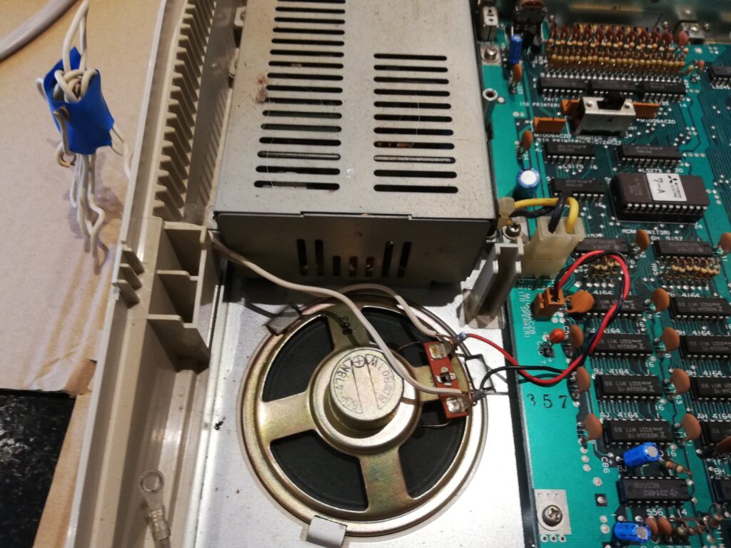
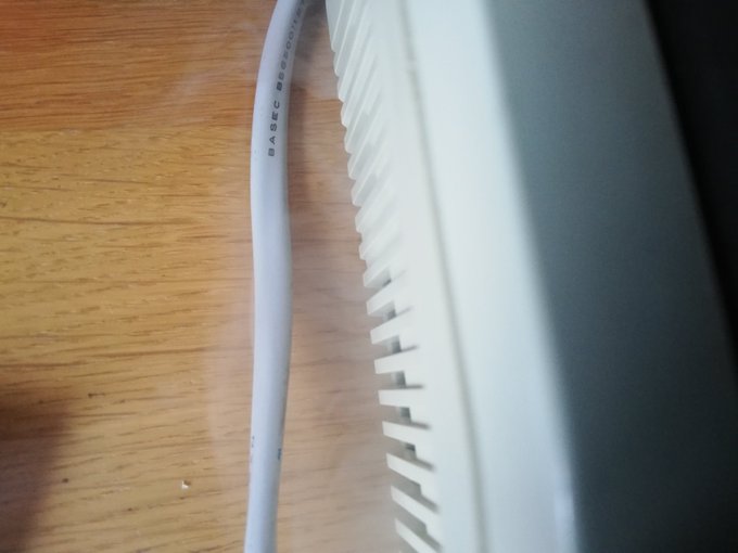
The mystery of the wires poking out from the case is solved. They’re loosely attached to the internal loudspeaker terminals – not even soldered on. Subsequent testing shows that the speaker is faulty, but intermittently. I remove the wires and order a replacement 77mm 8 ohm, 1 watt speaker for around £4.50 including postage from a well-known auction website.
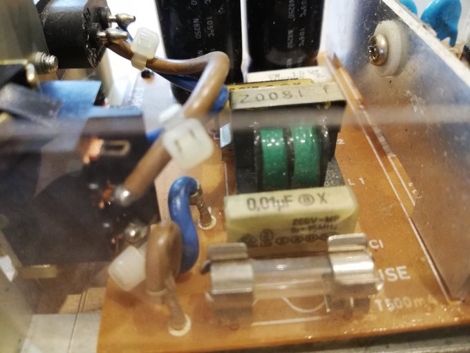
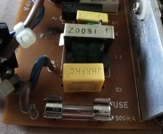
Next job is to remove the power supply, give it a visual inspection and check it with a multimeter before even thinking about powering the computer on. It should be delivering a constant 5v DC if it’s working properly. The visual inspection is generally fine – but the plastic casings on the filter capacitors (C1 and C2) are cracked. Hmmm.
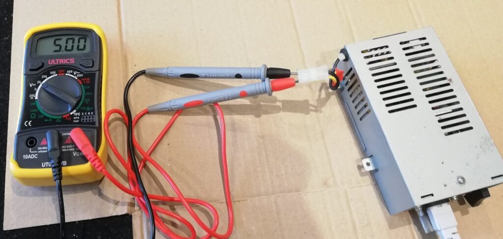
Checking the psu with a multimeter suggests all is well – a steady 5v is being generated. I decide to take a punt on the filter capactiors holding out (but order a couple of spares just in case – another £3). They’re not necessary for the operation of the power suppy, so I could have just removed them, but I like authenticity!
Time to give everything a good clean. As the plastic casing isn’t stained, I decide that a gentle soak in a mild detergent is all that’s required. I avoid disassembling most of the keyboard by using cotton buds to remove the grime off the keys – and underneath. One spring escapes across the kitchen as I remove one of the keycaps, but is found and easily refitted. Gentle puffs of air and careful work with a cotton bud removes the remaining clumps of dog hair. A few dabs of isopropyl alcohol clean up the expansion port contacts and the rest of the metalwork. The cassette recorder tape heads get treated to some special stuff acquired from HMV ages ago.
Time to test. After reassembly, the MZ-700 powers on successfully, speaker beeps, and rgb output looks good. But then one of the suspicious filter capacitors decides to explode. Fortunately it’s not too smelly.
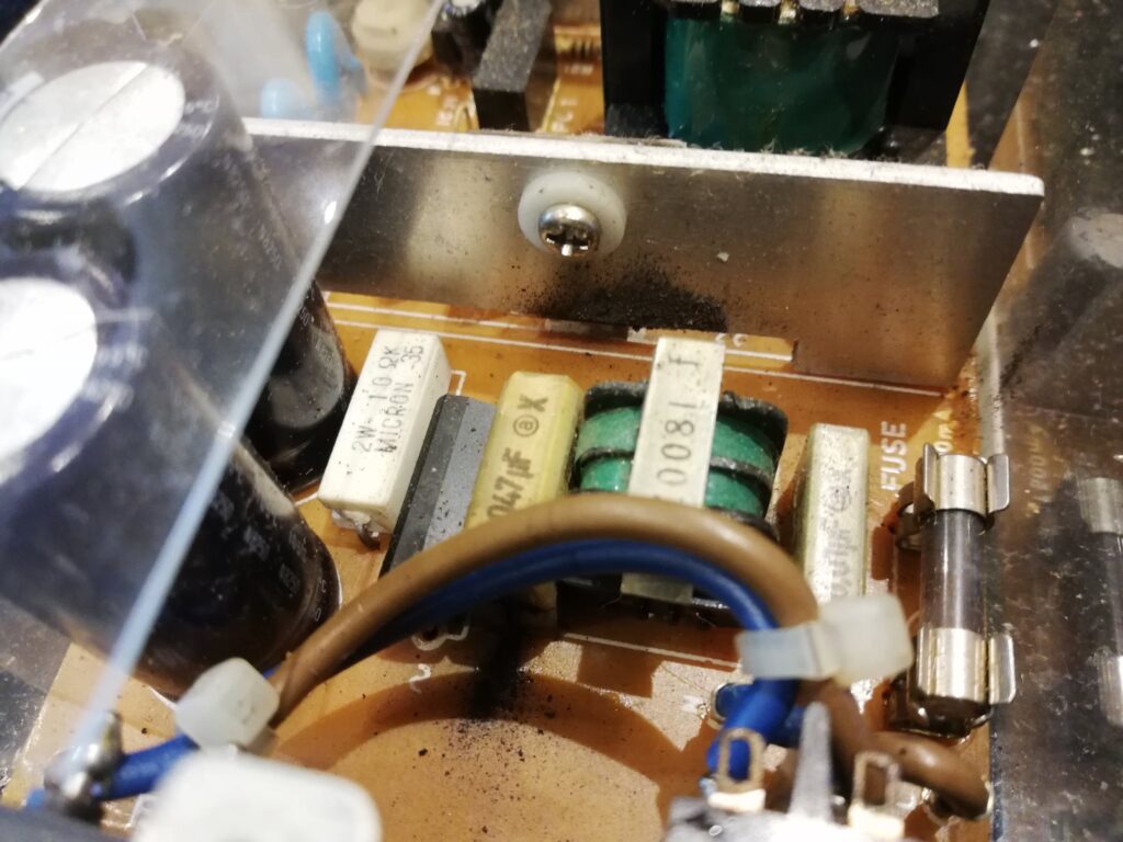
Opening up the machine I see that it’s a failed filter capacitior C2, rather than C1. The 500mA fuse has done it’s job of protecting the electronics and has also blown.
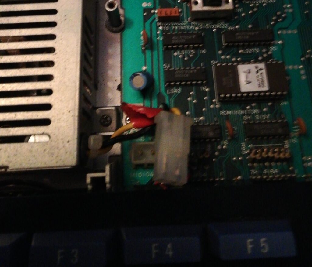
I remove both of the filter capacitors, replace the fuse and retest with the multimeter. 5v again. Reassembling the machine I plug it back into my monitor, turn it on and … nothing happens. Disassembling the MZ-700 (I’m getting good at this by now) I spot the problem.
Reassembly time again. This time all is well, and the cassette deck is able to load the BASIC interpreter at the first attempt.
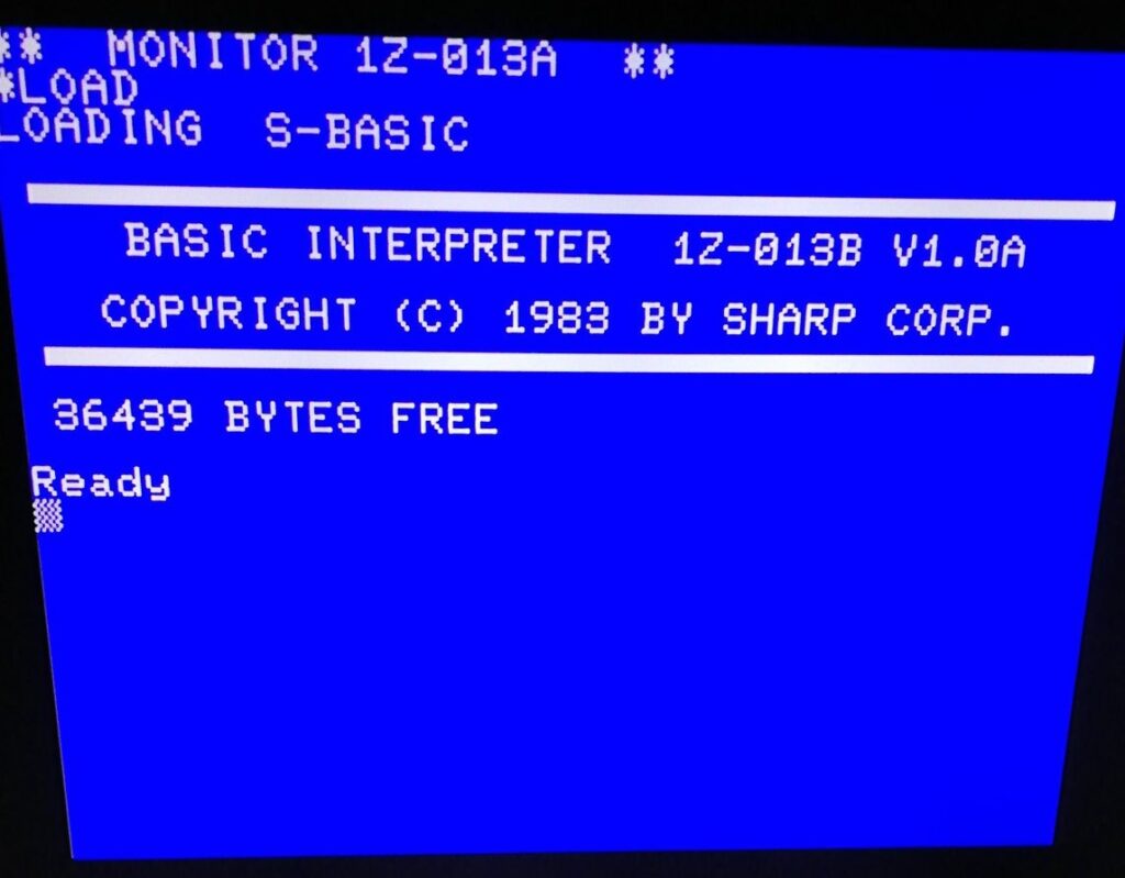
A few days later I went through the whole disassembly / reassembly process again to replace the filter capactiors. They should be good for another 30 years or so with luck.
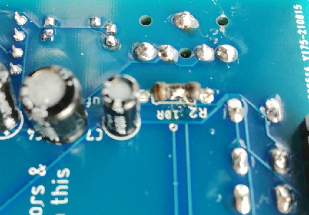
My attempt at building a tape deck replacment from scratch using a circuit board and an arduino I had lying around has failed. I’ve clearly got a short circuit in my soldering somewhere, as it’s twice blown a 10 ohm resistor within seconds of power on.
At the time of writing, I’ve yet to fit the replacement internal speaker. I’m also going to experiment with a pre-built SD card alternative to the tape deck – an MZuiTape. It should arrive at some point in the next few days.
28-11-2021: I’ve replaced the faulty internal speaker. Perhaps the need to remove nearly every single screw from the machine to replace the speaker was the main reason it had been modified!